In this post we will be talking about this MAX4466 microphone amplifier module, right? So this is a tiny little circuit that can amplify weak sound signals from an electret condenser microphone (ECM).
That means it is going to take a very small electrical signal from the microphone and then boost it up so we can use it for different purposes like sound recording, voice detection, speech recognition and even sound-activated projects.
This one is really great because it has low noise so it does not create too much unwanted distortion. Also we can adjust the gain with a small screw potentiometer, meaning we can control how much amplification we want. So now let us get into the details:

What This MAX4466 Module Has and What It Does
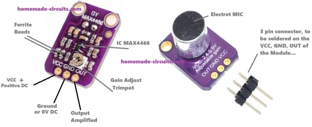
Amplifier IC: This uses the MAX4466 which is a low-noise operational amplifier made especially for microphones.
Built-in Electret Microphone: So it already has a tiny ECM microphone soldered on the board itself.
Adjustable Gain: We can make the amplification high or low from 25x upto 125x using the onboard potentiometer.
Low Noise Performance: The circuit is adjusted for giving clear audio which means that it will not add too much hiss or unwanted background noise.
Works With Different Voltages: It can work with any power between 2.4V and 5.5V so it is great for microcontrollers.
Analog Output: That means the output is a varying voltage which refers to the sound intensity and we can hook it up to an ADC (Analog-to-Digital Converter) or an audio amplifier.
How This MAX4466 Module Works, Step by Step
So this module takes sound, processes it and then gives out an amplified signal. Here is how that happens:
Sound enters the electret microphone which converts the air vibrations (sound waves) into small electrical signals.
This tiny electrical signal is too weak so it needs amplification.
Now the MAX4466 amplifier IC inside this module takes this weak signal and boosts it.
The output pin (OUT) then gives us this amplified sound signal as an analog voltage which we can use for more processing.
That is the basic working of this module. The louder the sound, the higher the output voltage and the quieter the sound, the lower the output voltage.
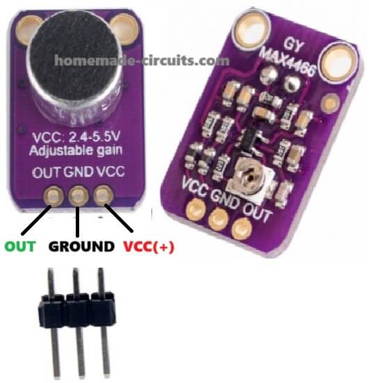
Pin Details – Where We Connect Things
| Pin | What It Does |
|---|---|
| VCC | We connect this to power (2.4V - 5.5V). It powers the whole module. |
| GND | This is the ground connection. We must connect it to GND of our circuit. |
| OUT | This is the analog output signal. We take this signal and connect it to Arduino, an ADC, or an audio amplifier. |
Now one more thing is here – the gain control potentiometer. This tiny screw-like thing on the board lets us increase or decrease the gain (amplification strength). That is useful because sometimes we want high amplification and sometimes low, depending on our project.
How to Use the MAX4466 Module – Step-by-Step Guide
Interfacing MAX4466 Microphone Amplifier Module with Arduino
Now let us say we want to use this MAX4466 module with an Arduino, right? so Here is how we connect it:
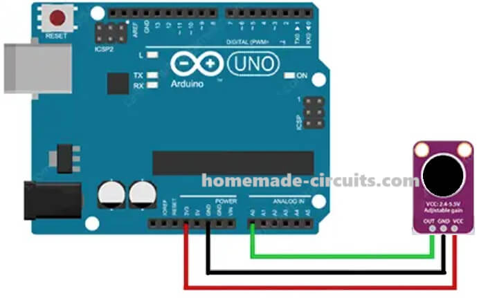
| MAX4466 Pin | Arduino Pin |
|---|---|
| VCC | 5V |
| GND | GND |
| OUT | A0 (Analog Pin) |
Then we write a small Arduino code to read the microphone output and see the sound levels.
Arduino Code to Read Microphone Output
const int micPin = A0;

void setup() {
  Serial.begin(9600);
}

void loop() {
  int soundLevel = analogRead(micPin);
  Serial.println(soundLevel);
  delay(10);
}
So now analogRead() is reading the voltage level from the microphone.
Serial.println() prints these values in the serial monitor.
When the sound is loud then the value is higher but when the sound is quieter then the value is lower.
Using MAX4466 with an Audio Device
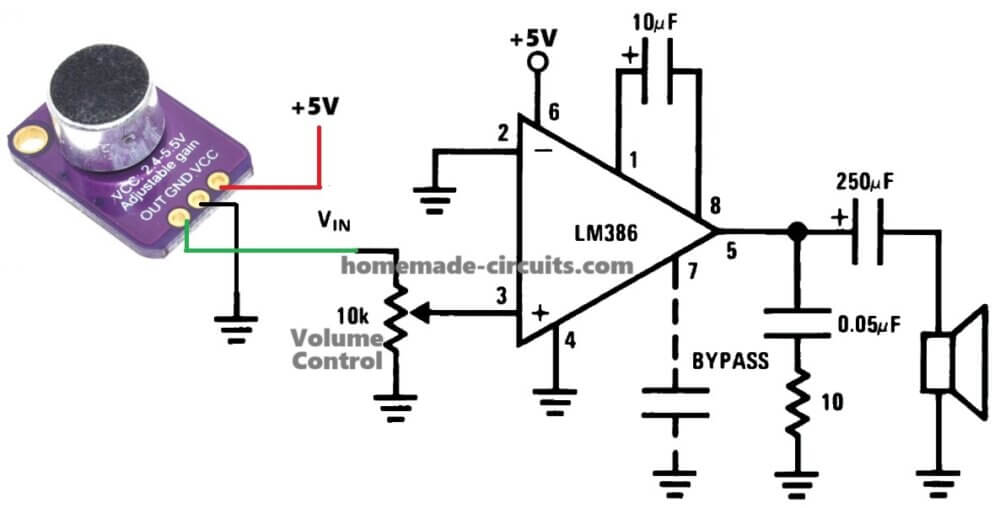
Now maybe you do not want to use an Arduino but want to listen to the sound directly, right? So In that case:
We take the OUT pin and connect it to a small audio amplifier with speaker such as LM386 amplifier circuit.
We power the module using 5V.
We adjust the gain using the potentiometer to get the best sound quality.
This way we can capture and hear sounds properly.
How to Adjust the Gain?
Now here is an important thing – Gain Control.
There is a tiny screw potentiometer on the board that we rotate to adjust gain.
Turn clockwise – Makes gain bigger by (up to 125x).
Turn counterclockwise – Makes gain smaller (down to 25x).
If the gain is too high then the sound may become distorted. If it is too low then the output might be too weak. So we must set it correctly based on our requirement.
Where Can We Use MAX4466? – Applications
This module is very useful in many projects. Some examples:
- Voice Recognition – Can be used in AI-based speech recognition projects.
- Sound Level Detection – Used to measure ambient noise levels.
- Security Systems – Works in spy microphones and intruder detection.
- Sound-Activated Circuits – Robots, lights, or alarms triggered by sound.
- Wireless Microphone – DIY low-noise audio systems.
So we can use this module in different ways as depending on what we want.
Comparison – MAX4466 vs Other Microphone Modules
Now if we compare MAX4466 with some other common microphone amplifier modules then this is what we get the results:
| Feature | MAX4466 | LM386 | MAX9814 |
|---|---|---|---|
| Gain Control | Yes | No | Yes (AGC) |
| Noise | Low | Medium | Very Low |
| Output | Analog | Analog | Analog |
| Voltage | 2.4V - 5.5V | 5V - 12V | 2.7V - 5.5V |
| Ideal Use | Low-noise audio | Basic amp | Professional audio |
So the MAX4466 looks better than LM386 because it has lower noise and an adjustable gain but if we need automatic gain control (AGC) then MAX9814 appears to be better.
Common Issues and Fixes
| Problem | Solution |
|---|---|
| No output / very weak signal | Increase gain using the potentiometer. Check power supply connections. |
| Distorted sound / too loud | Reduce gain and make sure input sound is not too strong. |
| Too much background noise | Use a shielded cable to avoid interference. |
| Low signal on Arduino | Use a DC bias circuit to center the waveform around 2.5V. |
Circuit Diagram
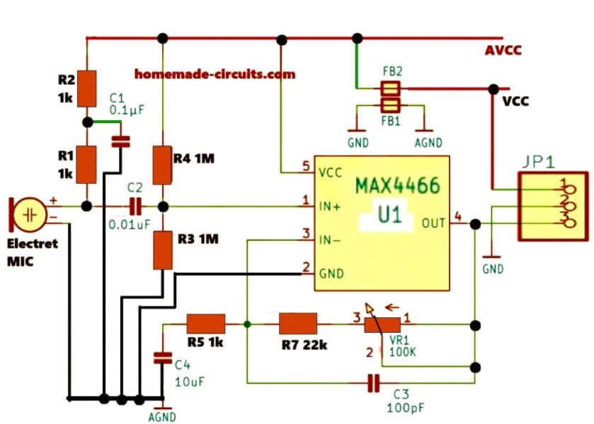
Explanation of Each Part in MAX4466 Microphone Amplifier Module Circuit
Now we got a circuit here that is working with a MAX4466 operational amplifier, right? This chip is mainly designed for picking up very weak signals from an electret microphone so we have to use it properly, that is why we need to see what every part is doing, step by step.
Electret Microphone (MIC)
So first we got the electret microphone, this is the main sound sensor in the whole setup. It listens to sound waves in the air then converts that into a very tiny electrical signal but this weak signal is not enough, so we need amplification.
Now this microphone does not work alone, it needs some voltage to keep it running, so that voltage is given by two resistors, R1 and R2, right?
Resistors (R1, R2 - 1kΩ)
These two resistors R1 and R2, they work together to create a voltage divider.
That means they take the supply voltage and split it in such a way that the microphone gets a stable direct current bias. Without this bias voltage, the microphone will not work properly, ok? So we must have them there.
Capacitors (C1 - 0.1µF, C2 - 0.01µF)
Now we got two capacitors here C1 and C2. They are playing different roles.
C1 (0.1µF): This one is used for filtering. If there is some unwanted high-frequency noise creeping in then this capacitor helps to remove that.
C2 (0.01µF): This one is important because it works as a coupling capacitor. It means it blocks any direct current voltage that might be there and allows only the actual alternating current signal (which is the audio signal) to go inside the amplifier. Without this, then the amplifier would not function correctly.
Resistors (R3, R4 - 1MΩ)
Now we got two more resistors R3 and R4 and these are quite large in value, 1MΩ each, right? So Their job is to provide very high input impedance to the MAX4466 operational amplifier.
We need that Because if the input impedance is too low then the microphone signal will not be able to drive the operational amplifier properly. So these resistors ensure that the input is correctly biased and ready for amplification.
MAX4466 Operational Amplifier (U1)
Ok, now we reach the heart of the circuit, the MAX4466 operational amplifier.
This is the main chip that does all the work. It is a special operational amplifier made for low-noise audio applications which means it takes the weak microphone signal and amplifies it without adding too much noise. This is very important because if there is too much noise, then the audio quality will be bad.
Resistors (R5 - 1kΩ, R7 - 22kΩ)
Now these two resistors R5 and R7 they are playing an important role in setting the gain of the amplifier.
R5 (1kΩ): This one helps in keeping the gain stable and preventing oscillations.
R7 (22kΩ): This resistor is the main one that sets how much amplification the circuit is providing. If this value is increased then the gain will also increase, and if it is decreased then the gain will go down.
Potentiometer (VR1 - 100kΩ)
Now we got this variable resistor which we call a potentiometer VR1. This is for manual control. By turning this we can increase or decrease the gain of the amplifier.
So if we want to boost the audio signal then we turn it one way and if we want to reduce the gain then we turn it the other way. This gives us flexibility in adjusting the amplification level.
Capacitors (C3 - 100pF, C4 - 10µF)
Now these two capacitors are here to take care of stability and noise reduction.
C3 (100pF): This one removes any unwanted high-frequency noise from the output.
C4 (10µF): This capacitor is used in the power supply line to filter and stabilize the voltage. If the power supply is not stable, then the circuit will not work properly, so this capacitor helps to smooth out any fluctuations.
Ferrite Beads (FB1, FB2)
Now we got these ferrite beads FB1 and FB2 and they are there for noise reduction. They block high-frequency interference in the power supply lines. Why is this needed? Because if high-frequency noise mixes with the signal then it can mess up the audio output so these beads stop that from happening.
Connector (JP1)
Now we come to the output part. This JP1 is the connector where we take out the amplified audio signal. We can connect this output to another circuit maybe an analog-to-digital converter if we are using a microcontroller or we can connect it to a speaker module for direct output.
Understanding AVCC, VCC, GND, and AGND
Now in this circuit, we got different power supply connections and they all have different jobs. Let us see what they do.
VCC (Voltage Common Collector)
This is the main power supply for the whole circuit, ok? Normally it will be either +5V or +3.3V depending on the design and what system we are using.
AVCC (Analog VCC)
Now AVCC is a separate voltage supply that is used only for analog parts of the circuit. Why do we need a separate analog power? Because if digital circuits create a lot of noise then that noise can mix with the microphone signal and we get distortion. So AVCC keeps the sensitive analog signals clean.
GND (Ground)
This is the main ground for the whole circuit. Every component uses this as a reference for voltage.
AGND (Analog Ground)
Now this is a special ground only for the analog part of the circuit. It is kept separate from the digital ground to avoid noise problems. When we separate analog and digital grounds then we get a cleaner signal.
Conclusions
So now you understand everything about the MAX4466 microphone amplifier module. This is super useful for any sound-based project, whether we want to detect sound, record it or even hear it live.
If we need a small, low-noise microphone amplifier that works with Arduino, Raspberry Pi, or even audio systems then MAX4466 Electret Microphone Amplifier module is a great choice.
Need Help? Please Leave a Comment! We value your input—Kindly keep it relevant to the above topic!